🔍

CDES Preparation

Making Heated and Equilibrated Gases

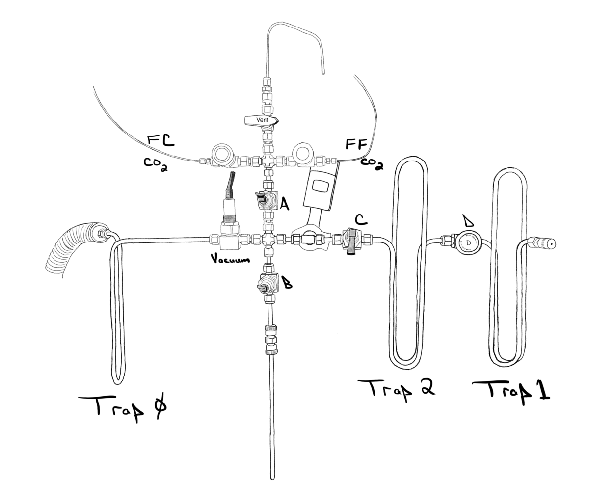
This method describes how to make equilibrated and heated gases used to create the carbon dioxide equilibrium scale (CDES) for calibration of our carbonate clumped isotope thermometer. Equilibrated gases are made by putting carbon dioxide (CO2) and water (H2O) into a flame-sealed tube and allowing them to reside together at specific temperatures for at least a week. The types of CO2 and H2O are referred to with two letter codes. The two types of CO2 are FC (Fermented Corn) and FF (Fossil Fuel). The water types are EN (enriched), DI (deionized water from the tap), and SP (south pole). The temperatures we use are 4 °C (refrigerator), 25 °C (lab temperature), and 60 °C (drying oven). The heated gases are created by putting dry CO2 into a sealed quartz tube and heating it to 1000 °C.
Setup

In this section you are gathering materials and getting everything is ready. Use the photos to help you locate and prepare appropriate materials. The steps below will walk you through the process. Make sure the CO2 cylinders are on. Waters are located in the single door refrigerator. CO2 / H2O equilibrations are loaded into pyrex tubes. You will also need to locate dewars that are among the smaller sizes as well as a lab jack.

Tube type and size

Tube cracker
Tube cracker used to make sure 1/4" pyrex tubes are sized properly. Ensure the tips as well as the tube body slide though the ultra-torr fitting.
Quartz and pyrex tubes
Quartz and pyrex tubes. These are located a the drawer under the automated carbonate prepline.

We use pyrex and quartz tubes and both of those types can be 1/4" or 6 mm. It is difficult to tell them apart of they are all mixed together. Use 1/4" pyrex tubes for CO2 / H2O equilibrations if they exists, BUT you should ensure each 1/4" tube slides easily through the lower tube-cracker ultra-torr fitting and that both tips of the tube are not flared and also easily slide through the fitting. You can also use 6 mm pyrex tubes for CO2 / H2O equilibrations but we generally try to reserve that size for samples ready for the Polly mass spectrometer. For the heated gases, use 1/4" quartz and 6 mm quartz. We need both sizes and they need to be kept separate. Wear nitrile gloves when working with quartz, not to protect you, but to protect the quartz from your sweaty hands. If you need to make tubes, refer to our SOP and video on making tubes. When making quartz tubes, use the eye protection specific for quartz, use the larger orifice torch tip, and use "Method 2" in the "Making tubes" SOP.

Prepare Manifold

  1. With the pollyprep computer, use the Labview software to turn "Glass Line in Use" ON and turn V2 OFF (see photo below).
  2. With the manifold itself, set all valves to the Evacuation state (see photo).
  3. Wait for the gauge to drop below 6E-3 Torr.
  4. Open the main valve on the CO2 cylinder(s) but leave the regulators alone.
  5. CLOSE valves A and B and leave the Vacuum valve OPEN.
  6. Open either FC or FF, wait 10 seconds, then open the Vent valve. This allows the CO2 to flow out the vent to purge the line with fresh CO2.
  7. Freeze the pump-side liquid nitrogen trap with a tall dewar and lab jack. This should bring the gauge below 3.0E-3 Torr.
Preparing the manifold photos.
Labview setup buttons
Labview setup buttons. Labview is on the computer that controls the carbonate prepline. Make sure "Glass Line in Use" is ON and "V2" is OFF.
Manifold showing all valves closed
CDES gas preparation manifold showing all valves closed. This is the state you should find the line in and the state you should leave it in.
Manifold showing valves in evacuation state
Manifold showing valves in evacuation state.
Manifold pressure / vacuum gauge
Manifold pressure and vacuum gauge. Units are in Torr. Note the "E" exponent, so 7.57E-2 Torr is 0.0757 Torr or 75.7 mTorr. You will use this gauge to assess when the manifold is ready for the next sample (e.g. the reading will be below 3.0E-3 Torr) and to assess the amount of CO2 (e.g. approximately 3.0E+2 Torr).
Toggle valve in closed and open position
Toggle valve in closed and open position. This applies to valves A, B, and Vacuum.
CO2 gas regulators used in CDES preparation
CO2 gas regulators used in CDES preparation. These are located on the south wall near the single door refrigerator.
CO2 gas cylinders used in CDES preparation
CO2 gas cylinders used in CDES preparation. These are located on the south wall near the single door refrigerator. These are the valves to be opened and closed.
Valve configuration for purging the FC CO2 line
Upper manifold valve configuration for purging the FC CO2 line.
Valve configuration for purging the FF CO2 line
Upper manifold valve configuration for purging the FF CO2 line.
Entire manifold showing the pump-side liquid nitrogen trap
Entire manifold showing the pump-side liquid nitrogen trap (red arrow).

Get Organized

  1. If you are going to make both heated and equilibrated gases, prepare the heated gases FIRST. This is because we want to ensure the heated gases are COMPLETELY DRY.
  2. Locate all your materials. The photos below may help. You may need quartz and pyrex tubes, two small dewars, a lab jack, pipette and pipette tips, and water standards.
  3. If you are going to make CO2 / H2O equilibrations:
    • grab the pipette and make sure it is set to 200 µL.
    • find the two small dewars shown in the photo or at least some that are similar in size.
    • prepare -80 °C ethanol as in the polly prep SOP and accompanying video.
  4. Grab one water standard at a time. You do not need all three at once.
  5. Get a note started in the pollyprep daily log. Enter your name and what you will be making today.
CDES preparation setup photos. Use these photos to help you find everything while setting up to prepare CDES gases.
CDES water pipette drawer
Drawer that contains the pipette and pipette tips used in CDES preparation.
Pipette set to 200 micro liters
Make sure the pipette is set to 200 µL.
Waters used in CDES preparation
Waters used in CDES preparation. These are located in the single door refrigerator.
Small dewars used in CDES prep
Small dewars that are convenient to use with CDES preparation. These maybe moved around the lab depending on who used them last.

Heated Gases

Heated gases photos.
Scratches on quartz to indicate type of CO2
Use the tubing scorer to identify the contents of a quartz tube prior to placing in muffle oven. No scratches = FC_1000, two scratches = EN_1000, three scratches = FF_1000.
Quartz tubes in muffle oven
Quartz tubes in muffle oven spaced out from each other for easy grabbing with tongs when they are hot.
  1. Don nitrile gloves. This is not for your protection, but rather to keep the salts on your sweaty hands off the quartz, which will react with the quartz at high temperatures, pitting the side walls and potentially making it difficult to create a vacuum seal.
  2. With valve B closed, install a quartz tube
  3. Open valves B and Vacuum.
  4. Using the torch tip best with quartz (large #3 orifice), flame the quartz tube.
  5. Wait for gauge to drop below 3E-3 Torr.
  6. To fill a tube with CO2, close vacuum, close vent, open A, watch gauge and when it reaches the desired pressure, then close valve A. The desired pressures are between 253 to 328 Torr (gauge reads 2.53E+2 to 3.28E+2). This is equivalent to the amount of CO2 evolved from 6 to 8 mg of pure carbonate. youtube icon
  7. Close valve B.
  8. Freeze the tip of the quartz tube with liquid nitrogen.youtube icon
  9. Start the CO2 you are using (FC or FF) purging again by opening the Vent valve. The appropriate CO2 valve should already be open and valve A should already be closed.
  10. Wait 30 seconds after the tip of the tube freezes (the tip freezes when you see a flurry of boiling liquid nitrogen followed by calm) [link to video]
  11. While you are waiting, open Vacuum and Vent but keep valve B CLOSED.
  12. Use the torch to cut the tube about one finger width below the ultra-torr fitting.
  13. Repeat above steps until you have the desired number of "to-be-heated" tubes.
  14. If you are going to switch among FC and FF, while the new tube is pumping, put the entire line in the "Evacuation State" (see photo above) and drop the pump-side liquid nitrogen dewar to allow that trap to warm up.

Equilibrated Gases

Equilibrated gases photos.
Pipette tip inside pyrex tube
Pipette tip inside pyrex tube.
Dewar on a lab jack
Dewar on a lab jack showing approximate positioning if freezing the tip of the tube.
Equilibrated gas tubes with labels
CO2 and H2O equilibrating gas pyrex tubes with labels. Label should have the water and carbon dioxide types as well as the current date and pressure gauge reading.
Equilibrated gas tubes in dewar
CO2 and H2O equilibrating gas pyrex tubes in dewar in refrigerator. A similar dewar exists in the 60 °C oven.
  1. Make cold -80 °C ethanol. , see a polly prep SOP and accompanying video. Check the temperature between each preparation. Try to keep it between -75 °C and -85 °C.
  2. Pipette 200 µL of your desired water (SP, DI, or EN) into a 1/4" or a 6 mm pyrex tube.
  3. Arm centrifuge or otherwise fling as much of the water that is stuck to the side walls of the pyrex tube to the bottom.
  4. Dip the tip of the tube into the -80 °C ethanol until the water is frozen.
  5. With valve B CLOSED, install tube into ultra-torr fitting.
  6. Place -80 °C ethanol dewar below tube with a lab jack and submerge the tip of the tube in the cold ethanol.
  7. Open valve B.
  8. Very lightly flame the tube to help remove residual liquid water from the sides of the tube.
  9. Raise pump-side liquid nitrogen dewar very slightly (~1 cm).
  10. Wait for gauge to drop below 5E-3 Torr
  11. To fill a tube, close vacuum, close vent, open A, watch gauge and when it reaches the desired pressure, close valve A. The desired pressures are between 253 to 328 Torr (reads on gauge as 2.53E+2 to 3.28E+2). This is equivalent to the amount of CO2 evolved from 6 to 8 mg of pure carbonate. youtube icon
  12. Close valve B
  13. Replace the ethanol dewar with the liquid nitrogen dewar, ensure the tip of the tube is completely submerged in liquid nitrogen and wait for the tip to freeze. youtube icon
  14. Wait 30 seconds after the tip of the tube freezes (the tip freezes when you see a flurry of boiling liquid nitrogen) [created video]
  15. While you are waiting, open Vacuum and Vent but keep valve B CLOSED.
  16. Use the torch to cut the tube.
  17. Repeat above steps until you have the desired number of "to-be-heated" tubes.
  18. If you are going to switch among FC and FF, while the new tube is pumping, put the entire line in the "Evacuation State" (see photo above).

Cleaning up

When you are finished for the day, clean up and get the manifold ready for the next day.

  1. You do not need to install a new tube.
  2. Lower the vacuum pump-side liquid nitrogen dewar
  3. Put the line "Evacuation State" as describe and pictured above.
  4. You can leave it like this or you can wait until the gauge drops into the E-3 range and then close all the valves.
  5. On the labview software, turn "Glassline in Use" OFF and V2 ON
  6. SAVE YOU NOTE!!! if you were using the daily log on the pollyprep computer to make notes about today.
  7. Use a funnel to dump liquid nitrogen into one of the hand-held floor dewars.
  8. Use a funnel to dump ethanol back into the jug and put the jug of ethanol back in the freezer.
  9. turn off the torch
  10. put waters back in fridge
  11. wet pipette tips in drying oven
  12. generally cleanup space


Appendix - Archived Protocols

Glass Line Work - Archived

Glass vacuum line diagram
Diagram of the glass vacuum line in JHN 302B

Making Cylinder Heated Gases

Use the glass line to fill quartz tubes with reference gas. Creating tubes and heating them to 1000° and quenching them will imprint the gas with a stochastic isotopic composition.

  1. Pump down glass line
    1. Make sure MV3, MV7, MV8, MV9, MV10, and MV14 are closed.
    2. Open MV12, MV4, MV5, MV6, MV11, and MV13.
    3. Wait for G4 and G5 to reach minimum.
    4. For each glass valve and one at a time, rotate the stopcock to pump out the back of the valve, waiting for G4 / G5 to reach minimum.
    5. Return all glass valves to the open or closed state they were in prior to step ‘d’ and allow to pump.
    6. If G4 does not go below 20 mTorr, consider regreasing all stopcocks.
  2. Attach four quartz tubes onto MV7, MV8, MV9, MV10.
  3. Open MV7-MV10 to evacuate tubes.
  4. Thoroughly bake out tubes with torch while waiting for G4 to reach minimum.
  5. While pumping, make sure MV14 is closed, open MV15 and MV17 to vent CO2, wait 5 seconds.
  6. When G4 has reached minimum, close MV6, MV13.
  7. In quick succession, close MV17, open MV14 and watch G4 carefully, closing MV14 when G4 reaches target pressure (150 Torr).
  8. Close active tube valves MV7-MV10.
  9. Open MV13 and MV6.
  10. Freeze sample tubes with liquid nitrogen.
  11. Wait 30 seconds after tube is frozen.
  12. Seal quartz tube with torch.
  13. Put up to 8 tubes into the muffle oven and set to 1025 °C (setting of 1025 = 1000 actual °C).
  14. Once the oven reaches 1025, wait at least 2 hours.
  15. Once at least 2 hours has passed, you will need to remove the hot quartz tubes while the muffle furnace is at 1025 °C to quench the CO2.
  16. Wearing appropriate protective gear, and using the long heavy metal tongs, remove the quartz tubes from the muffle oven, placing hot quartz on protective ceramic plates.

Making Water Equilibrated Gases

Use the glass line to prepare tubes with water / carbon dioxide for oxygen equilibration at appropriate temperature. After several days, carbon dioxide will have a desirable oxygen isotope ratio. 

  1. See step 1 in ‘Making Cylinder Heated Gases’ above.
  2. Choose either the DI or EN2 water standards from refrigerator.
  3. Pipette 200 µL into a ¼” pyrex tube, fling or arm centrifuge water to bottom of tube, and place just the tip in a -80 °C ethanol slush.
  4. Once it is frozen, attach tube (keeping the tip in the slush) to MV7-MV10 and open MV7-MV10, waiting for G4 to reach minimum.
  5. While pumping, make sure MV14 is closed, open MV15 and MV17, wait 5 seconds.
  6. When G4 has reached minimum, close MV6, MV13.
  7. In quick succession, close MV17, open MV14 and watch G4 carefully, closing MV14 when G4 reaches target 150 Torr.
  8. Close active tube valves MV7-MV10.
  9. Open MV13 and MV6.
  10. Freeze sample tubes with liquid nitrogen.
  11. Wait 30 seconds after tube is frozen.
  12. Seal pyrex tube with torch.
  13. Label tube as either DI or EN2 and place into 60 °C oven or 4 °C refrigerator.

Glass line - If backgrounds on the glass line are higher than normal, check manual valves. If they are difficult to turn and small bubbles form, they need to be re-greased. To re-grease close MV12 and MV13. Open MV10 and depressurize the glass system. Turn Valves MV4 and MV11 360° to vent out the backside. They should now be easier to remove. With gloves, clean off any excess grease surrounding the valve, put a thin film of M grease on your finger, and coat the outside of each stopcock with new grease. Place them back in their socket and turn them so the backside of the valve will evacuate. Close V0, V1, V2 and V10. Open MV12 and MV13. Complete re-greasing the rest of the valves with the same principle of depressurizing the back of valve to remove, re-grease, re-pressurizing backside of valve.  Complete until all valves have been re-greased and the glass line is holding pressure. 

Glass line not holding vacuum – Close V0, V1, V2, V10 and open MV12, MV13. Evacuate backs of valves MV4 and MV11 – wait until G3 reaches bottom. Close MV11, MV6, and open MV5 and MV4. Pump down space, turn MV6 to pump out the backside of valve. Once G3 reaches bottom, close MV6, and turn MV5 around to evacuate the back and GT2 through MV4. Once no deflections occur on G3, open MV4, MV5, MV6, MV11. One at a time, evacuate the backs of valves MV7-MV10. When this is all completed, evacuate backs of valves MV7-MV10 at once until G4 reaches a minimum. If the vacuum does not hold when MV4 and MV11 are closed, try to isolate problem and re-grease valves. 

High Vacuum Pressure is too high but stable – Open V16 first (the turbo exhaust) before opening V15, assuming that the rough pump is pumping down.

Signature

I have read and understood the present SOP and, before starting work outlined in the present SOP, I will complete all required training.

Last updated: 2021-06-11 11:35:40