Solid Sulfur Isotope Analysis
Introduction
This document outlines how to run Shrek for sulfur isotope analysis of solid materials using the Eurovector elemental analyzer. Shrek, a Finnigan MAT253, is set up as a continuous flow isotope ratio mass spectrometer for the analysis of carbon, nitrogen, and sulfur isotopes. It has two elemental analyzers (EAs), a custom low-N setup, and two peripheral / mass spectrometer interfaces (Conflo IIIs). Use the Terse Procedure section if you already have a good idea of what you are doing. Use the Exhaustive Protocol section for more thorough descriptions. This flow diagram may be helpful.
Note - We are actively updating this procedure given the recent change to cryofocusing the SO2 after the equilibration column. The target amount of sulfur is currently set to 5 µg but this will likely change.
Safety
We add a combustion aid called vanadium pentoxide to each sample tin. Vanadium pentoxide is particularly hazardous and you must read and sign it's chemical SOP.
Appropriate precautions should be taken to protect yourself against the high temperatures of the elemental analyzer and the reagents used therein. Users should wear safety glasses and leather gloves when changing the insert. Preparing the insert and the combustion / reduction / desiccant columns should take place in the hood and users should wear nitrile gloves. Users are expected to know the contents of the MSDS for each of the ingredients of the columns and know what to do in case of exposure or spillage.
Terse Procedure
- Prepare samples and standards into as small a tin as possible
- In a fume hood, add sample or standard with vanadium pentoxide and tin powder to a new tin
- Clean up vanadium pentoxide spills appropriately
- Make certain the previous run has finished
- Note the N2 background with the dilution off
- Consider if a new insert, new combustion column, or new desiccant should be installed before proceeding
- Load samples
- Complete sequence table
- Purge all atmospheric air out of autosampler
- Complete Daily Log
- Start your run
- Use shrekS.m on matlab to reduce your data then run shrekS_cyro.m in matlab
Exhaustive Protocol
| Standard | Material | Sulfur (%) | Target (mg) |
| Ag2S | Silver sulfide | 12.94 | 0.039 |
| ZnS | Zinc sulfide | 32.91 | 0.015 |
| BaSO4 | Barium sulfate | 13.74 | 0.036 |
| SA | Salmon | 0.8 | 0.625 |
| MAL | Malachite Lake Sediment | 0.2 | 2.5 |
Weighing samples and standards
Samples and standards are weighed into tin capsules. Consult the microbalance method. The addition of vanadium pentoxide and tin powder happens in a fume hood. The target weight for Shrek sulfur is 5 µg of S per capsule. This target weight is optimal though the instrument can run lower and higher amounts of sulfur. To determine target weights for your sample material, divide the elemental target weight (e.g. 5 µg S) by your percent (e.g. 2 % S in decimal form). This example, then yields 5 µg S / 0.02 = 250 µg of material.
Vanadium Pentoxide and Tin Powder
Vanadium pentoxide, V2O5, is a combustion aid that increases the abundance of oxygen immediately around the sample material when we want rapid and complete combustion. Given the toxicity of V2O5, we do not strictly control the amount and thus the ratio of sample/standard weight to Vanadium Pentoxide weight. Rather, we add a visually similar amount to each capsule. The V2O5 reagent does not have any sulfur in it and thus, having a standard amount is less important. The most important consideration is that oxygen is in excess and available during combustion.
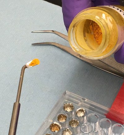
After you have all your samples and standards weighed into tin capsules and you are ready to add the V2O5, find a clean and clear hood (or make a hood so). Don protective nitrile gloves and a lab coat. Place your tray of weighed samples and standards into the hood. Also have in the hood, a second clean tray, the vial of vanadium pentoxide, two tweezers, two micro-balance type scoops, wipes, and the vanadium pentoxide waste container. You will be working at the hood for a while and may choose to have a stool to sit on. With the hood sash lowered so as to act as face protection, open the sample tray and vanadium pentoxide. Place a scoop of vanadium pentoxide into each tin. The draft from the hood may blow some of the vanadium pentoxide into the tray or the hood area. Leave this for later cleanup. Continue adding vanadium pentoxide into each tin until you are finished. Close the vial of vanadium pentoxide and wipe the utensil clean, discarding the wipe into the waste container. Now add a comparably sized scoop of tin powder to each tin. When finished, you should have an open tin with a weighed sample or standard packed into a smaller tin, a scoop of vanadium pentoxide, and a scoop of tin powder. Using the tweezers, grab the first tin, remove it from the tray, close it up tightly into a ball, and place it into the clean tray in the exact tray location that it was weighed into. Continue until all tins are closed and transferred to the clean tray. Close, secure, and label the tray as needed.
You have likely spilled vanadium pentoxide into the hood, the tray, etc and have a fair bit of clean-up to do. Make sure you have the waste container with you in the hood. Use paper towels and water or ethanol or spray soap to clean all of the vanadium pentoxide from the hood surface. These paper towels should go into the waste container. All utensils should be wiped clean, disposing of the wipes into the waste container. The 96 well tray likely has loose vanadium pentoxide in it as well. DO NOT USE THE AIR GUN TO BLOW IT OUT. Try to clean the tray by laying out one or two paper towels flat on the bench surface. Squirt ethanol into the wells while holding the tray inverted and over the paper towels. Repeat until the tray is clean. Allow the paper towel to dry in the hood, then place it in the waste container. If you can not clean the tray, place it in the waste container.
While historical tests sometimes suggest that vanadium pentoxide is not necessary, it is clear that the addition of both vanadium pentoxide and tin powder creates a hotter reaction space, increasing the chances of complete thermal conversion of sulfates to SO2.
Run Sequence
The goal of any run is to be able to calibrate measured δ34S values to the VCDT (Vienna Canyon Diablo Troilite) scale and to calibrate SO2 peak area to sulfur quantity.
A typical tray of 49 drops could proceed qtycal_BaSO4 2x, qtycal_BaSO4 1x, qtycal_BaSO4 1/4x, qtycal_BaSO4 1/2x, 3 standards, 8 samples, 3 standards, 7 samples, 3 standards, 8 samples, 3 standards, 7 samples, 3 standards.
However, this sequence is still being developed with the cryofocusing method. It will likely have a reduced number of drops since our initial sample material will have glass fiber filters. It may also be that the 32 position carousel is used, in which case the number of drops is reduced to 31.
Previous Run
Check the Information box at the base of the IsoDat Acquisition screen to see if the previous run has finished. The information box is a play-by-play log of events that updates while the instrument is running. If the instrument was previously running and is finished, you should see a few rows indicating that the sequence finished, the last of which will have a green dot with white check mark, a time stamp, the word 'Sequencer', and the text "Sequence Finished !". It is a good idea to view the samples of the previous run as a first cut at checking for proper instrument functionality.
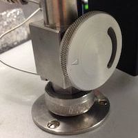
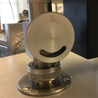
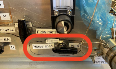
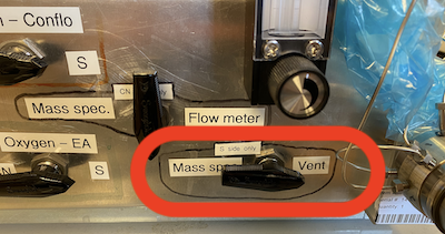
Valves
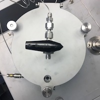
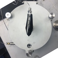
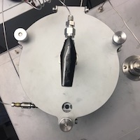
While you are loading samples you will be manipulating many valves. This section is meant to show these valves to you as well as show you all the different positions they may be in.


Instrument Preparation
Current instrument state - Before opening the instrument up to change the insert, change columns, or load samples, make a mental note of the N2 background and the carrier flow rate with the dilution OFF. Within Isodat Acquisition, change the gas configuration to N2 by using the drop-down menu in the lower left corner of the screen. Make certain all reference gases are off by clicking any Reference gas dark gray bars in the Conflo window on the left side of the screen. Turn the dilution OFF by clicking the dilution bar in the Conflo window on the left side of the screen. Note the m/z 28 signal and then turn the dilution back ON. The N2 background should be around 200 mV. On the Eurovector EA, press any arrow key to wake up the display and then scroll to the right (right arrow) until you see Carrier. It should be about 9 mL / min.
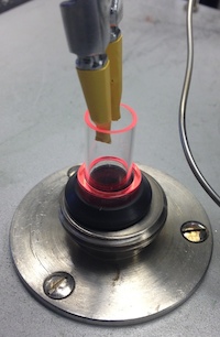
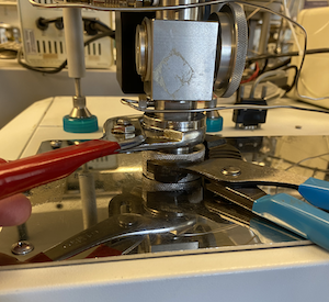
Replacing the ash insert - If you are not going to replace the combustion column (as described in the below section), then you will need to replace the ash quartz insert. The insert is replaced before every run. It may not be full, but accumulated ash seems to affect the sulfur results. Prepare a new insert by packing 2-5 mm of quartz wool at the base (the side with the vent slits). Take the new insert and the pyrex casserole dish and place them on a stool next to the Eurovector EA. Assuming the isolation valve is already open, SLOWLY vent helium from the EA by pointing the autosampler lid valve towards the vent (away from vacuum). Use both pair of channel-lock pliers to loosen the collar that attaches the autosampler to the top of the combustion column. Wearing leather gloves and eye protection, remove the collar and autosampler from the top of the combustion column and shift this as far back as possible so that the top of the combustion column is visible and free to access. Adjust the pliers for a smaller diameter, use the insert removal tool to grasp the inside of the insert and begin pulling it out, and then grab the insert with the pliers to remove it completely and place it into the pyrex dish. If quartz wool was stuck to the bottom of the insert, replace it with more quartz wool. You can install the new insert by grabbing the top with your gloved fingers and gently sliding the insert into place (pushing the quartz wool into place with the insert if you had to install more). Blow off the rubber seal. Replace the autosampler and tighten the collar, first with your fingers, and then with both pair of pliers. Close the isolation valve.
Replacing the combustion column - The combustion column is a 45 cm quartz tube and heated from the EA furnace. The combustion column is heated to 1050 °C, and is packed with quartz chips and reduced copper. The reduced copper is used to remove excess O2 from the Helium stream. Quartz chips at the top of the combustion column are used as a temperature buffer so the copper does not melt from the heat generated while combusting samples. Wear nitrile gloves. The combustion column is packed from bottom to top as follows: 6 cm of empty tube, 0.5 cm quartz wool, 10 cm reduced copper, 0.5 cm quartz wool, 5.5 cm quartz chips, 0.5 cm quartz wool. The combustion column should be replaced after 80 normal samples. In general, replace the combustion tube after THREE 31-drop runs. The reduced copper is the limiting reactant. If you adjust the amount of oxygen used per sample, you should try to estimate how long the column will last.
Once you have the combustion column packed, consider the desiccant column and if it should be changed do it at the same time (see below section). When you are ready to install the combustion column, take the new column and the pyrex casserole dish and place them on a stool next to the Eurovector EA. Turn the mass spec valve to vent. Assuming the isolation valve is already open, SLOWLY vent helium from the EA by pointing the autosampler lid valve towards the vent (away from vacuum) and you will hear a hiss as helium carrier gas is vented into the room. Use both pair of channel-lock pliers to loosen the collar that attaches the autosampler to the top of the combustion column. Wearing leather gloves and eye protection, remove the collar and autosampler from the top of the combustion column and shift this as far back as possible so that the top of the combustion column is visible and free to access. Gently lift the combustion column from below by grasping the lower fitting and raising it up until you can grab the top of the quartz tube and o-ring firmly. Pull the combustion column straight up until it is completely free of the EA. Gently place the HOT combustion column into the pyrex dish and allow it to rest on the side rim of the dish. Remove the o-ring and install it on the new combustion column. If you are changing the desiccant column, do those steps now (see below). Slowly lower the new combustion column, with o-ring through the hot furnace area. Watch below the furnace area for the column to emerge into view. Blow off the end and insert it into the fitting while twisting the top of the column and pushing down to firmly seat it in the lower fitting. Replace the autosampler and tighten the collar, first with your fingers, and then with both pair of pliers. Close the isolation valve. Check for leaks using the leak detector and the EA flow rate.
Equilibration column - The equilibration column is heated to 900 °C and is only packed with quartz chips. The quartz chips uniformly exchange the oxygen from the sample gas to give all combusted materials the same oxygen isotope ratio in SO2. This allows for variation in mass 66 to be interpreted as variation in δ34S. This column generally does not need to be changed.
Replacing the desiccant column - The Desiccant column is packed with Magnesium Perchlorate to remove all water from the combustion and helium stream. Its placement between the two columns is to reduce the possible influence on the oxygen isotope exchange from H2O in the equilibration column. The frequency of replenishing the desiccant column really depends on the sample type. If you have a lot of organic material in your samples, this will generate more water during combustion, and the desiccant will need to be replenished more frequently. BaSO4 samples will not need replenishing as frequently. If you observe lots of fresh appearing magnesium perchlorate as you clean out the old desiccant trap, then you probably could have allowed it to stay in place longer.
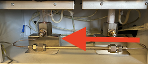
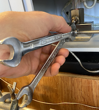
Place all supplies in the fume hood. Use nitrile gloves. Pack a new column by first making sure the empty tube is clean. Pack a small amount of glass wool (not quartz wool) into the end the arrow is pointing towards. Slowly add magnesium perchlorate using a scoopula. Use the vortexer to pack it down. Keep adding magnesium perchlorate and vortexing until about 1 cm remains from the top of the reagent to the top of the column. Pack glass wool into this 1 cm space. Blow off both ends with compressed air. Once you have a fresh desiccant trap packed and ready, prepare a combustion column as described above and while the combustion column is removed, install the desiccant column as described here. If you are NOT changing the combustion column, then make sure the isolation valve is OPEN and the 3-way valve has been slowly moved to the vent position. Loosen the fittings on either side of the desiccant column using 1/2" and 9/16" wrenches. Position the wrenches such that you only need to squeeze your hands together (see photo) so as to minimize the strain on the tiny 1/16" tubing. Completely remove the old desiccant column. Install the new column such that the arrow is pointing to the right which is the direction of helium flow. Finger tighten both fittings, then use the wrenches and the same squeezing technique. After replacing the desiccant column, check for leaks using the leak detector and the EA flow rate.
Gas Chromatography Column - The Gas Chromatography (GC) column is teflon lined stainless steel tubing packed with porapak QS and held at 105 °C. It is used to separate SO2 from other gas species. It generally does not need replacing or replenishing but may, on occasion, need baking out. Do this at 180 °C at least overnight and preferably over a weekend.
Loading Samples
Preparing the carousel - With the isolation valve closed (arrow pointing towards you), vent the autosampler by pointing the three-way valve on the lid towards the vent (away from vacuum). Loosen the three nuts that hold the lid in place (you may need pliers) until the nut assembly hinges and falls down. Open the autosampler lid. Check the carousel for debris and blow out as needed. If you are unable to clean the carousel with it in place, remove the carousel by pulling straight up while grasping the center portion. You can remove the three screws located on the underside of the carousel to remove the base plate. Use wipes with ethanol to wipe the carousel pieces clean. Wipe the body of the autosampler in the same way. If it is still dirty, you can soak the carousel in soapy water and scrub as needed. Reassemble the carousel when dry and replace into the autosampler body.

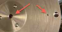
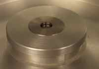
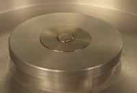
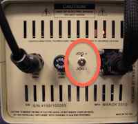
Autosampler alignment - Whether you remove the carousel for cleaning or not, you should check the alignment to ensure proper dropping of samples. Ideally, the carousel hole is lined up exactly with the base plate such that you can not see the base plate. It is always a good idea to advance the autosampler manually with the Costech control box to ensure proper alignment. Press "MANUAL ADVANCE" on the costech control box and the autosampler will advance one position. If you wish to advance multiple positions, wait 2-3 seconds between each push of "MANUAL ADVANCE". If the carousel is not exactly aligned, you will need to make fine scale adjustments with the "jog" switch. Toggling the Jog switch up (Jog +) will very slowly move the carousel in the positive direction (same direction as the manual advance button), while toggling the jog switch down (Jog -) will very slowly move the carousel backwards. YOU MUST ALWAYS FINISH YOUR JOG ADJUSTMENTS IN THE POSITIVE DIRECTION. If you move the jog switch at all, always finish these fine scale adjustments with one last "MANUAL ADVANCE" to ensure proper alignment.
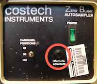
Load your samples - Using tweezers of your choice, carefully place samples and standards sequentially in the autosampler starting to the right of the hole (which may be position 50; e.g. start loading at position 1). Continue until all samples and standards are loaded. Now is a good time to make final adjustments on your sample capsules if they are very full. If they are touching multiple sides of the autosampler hole, you may want to squeeze them to be thinner and taller.
Close the lid - Wipe the o-ring with a wipe or your finger to remove any lint or debris. Close the lid and secure the bolts into place, making them finger tight. Rotate the 3-way lid valve to the evacuate position (see above for how) to pump out the atmospheric air from the autosampler. As it is pumping, you will need to keep tightening the lid nuts, again, to finger tightness. IT IS NOT NECESSARY TO USE A TOOL TO MAKE THE NUTS TIGHTER THAN FINGER TIGHT. Evacuate autosampler for 5 minutes. Proceed to next step while waiting.
Purging autosampler
- Within the mass spec software, Isodat, turn the dilution ON
- After the 5 minutes of evacuation, close the three-way valve
- Open helium purge valve and wait several minutes for helium pressure to build up inside the autosampler
- Turn 3-way valve to vent (you will hear a hisssssss), then close the 3-way valve
- Close the helium purge valve
- VERY VERY SLOWLY, while watching the carrier flow on the Eurovector EA front panel, open the isolation valve. As soon as you see the carrier flow begin to increase stop moving the isolation valve and wait for flow to stabilize. Once stable, continue SLOWLY opening the isolation valve. Continue this process until the isolation valve is completely open. If you open the isolation valve too quickly, the quartz wool inside the ash insert will be disturbed by the helium pressure change causing poor combustion for your run.
- Within Isodat, set the gas configuration to N2 and start a trace in instrument control
- On the Eurovector EA front panel, change the carrier pressure to ~200 kPa. This will hasten the purging of atmospheric air out of the autosampler. Within Isodat Acquisition, the dilution should already be ON.
- Start repeated purging of autosampler:
- SLOWLY move 3-way valve to the venting position (you will hear it hissssss) until the 3-way valve is completely in the venting position
- close the 3-way valve
- wait for Eurovector EA carrier flow rate to stabilize
- repeat one or two more times
- wait a minute or two
- repeat these steps until the N2 background is below 10 mV
- Turn dilution off
- Continue purging with 3-way valve until N2 stops increasing above 200 mV while venting
- Adjust Eurovector EA carrier pressure down to a set point of 30 kPa. This will usually result in an observed carrier pressure of about 35 kPa.
- Continue adjusting the carrier pressure until the observed carrier flow rate is 9 mL / min.
Eurovector Program
The Eurovector EA has 9 different saveable programs. We are currently using Method 7 as we develop the cryofocusing technique. The current settings in method 7 are:
- Carrier: 30 kPa
- Purge: 80 ml/min
- O2 vol: 60 mL
- O2 ΔP: 78
- Time: 9.9 sec (this is calculated based on above two)
- SMP: 5 (delay in seconds between oxygen pulse and carousel advance)
- Run: 30 (amount of time in seconds before a new sample can be started)
- Front: 1050 °C (combustion column)
- Rear: 900 °C (equilibration column)
- Oven: 105 °C (GC column)
To access and edit any part of the method parameters indicated above press MET, then use right or left arrow buttons to find the desired parameter, when it is flashing, use the up or down arrows to adjust as needed, then use the right or left arrows to scroll back until you see STO flashing, then press ENTER, then press MET to finish.
Sequence Table
On the left side of the screen, find the Sequence tab under the Browser window bar to open the appropriate sequence. Currently we are using SO2_Samples_Cryofocus.
Peak Center - The first column is the peak center column and it should have a check in every row. A peak center is accomplished by increasing the speed of ions exiting the source forcing them to sweep from one side of the faraday cup to the other and then by decreasing the speed of the ions forcing them to sweep past the faraday cup in the reverse direction. The software sets the speed of the ions (i.e. high voltage) such that the ions are hitting the middle of the faraday cup.
Amount - Enter sample mass under the Amount column heading. This will allow for the C and N content calculation.
Identifier 1 - Enter the appropriate standard and sample names under the Identifier 1 column heading. If you intend to use the 'shrek' matlab script, make sure to type the reference materials in appropriately and identically (e.g. BaSO4, Ag2S, ZnS).
Identifier 2 / Preparation / Comment - Use these columns to enter ancillary information you wish to stay with each sample or standard.
Method - Make sure the method is what you want it to be. Currently, for cryofocusing testing, we are using SO2_samples_cryofocus_automated.met. Sometimes we use SO2_samples_cryofocus_automated_NoEA.met; this _NoEA.met option simply drops the trap into liquid nitrogen for the same duration but does not advance the autosampler or introduce a pulse of O2. In this way, we can test for lingering SO2 present in the carrier stream.
Zeros - Its your choice to include zeros or not. One reason to include them is if you have high backgrounds due to a fresh insert, don't have time to let the backgrounds drop, but want to see the first drop combustion. Include 5-10 zeros after the first drop. Another reason to include zeros is to ensure the mass spectrometer is functioning properly. Here you would include 3-5 zeros near the beginning of the run (probably after the first drop) and again at the end of the run.
Daily Log
The lab uses a daily log for each instrument or preparation line to allow users a first glance at the readiness of the instrument. By comparing the current state of the instrument to historical states, you are more informed about the instrument and whether or not it is functioning properly and ready to run your samples.
Each daily log is web based and browser accessible. No link is provided here by design. Open the browser on the controlling computer and you should see at least two tabs already open. One tab is this SOP and the other is the daily log. If the browser has more than two tabs open, it may have additional SOPs. Use the bookmark toolbar as needed if tabs have been closed.
Work through each cell of the daily log. If you are uncertain where to find certain information, hover over the column header tip, denoted by a ⓘ symbol.
Make certain to press the 'save to log' button when you are finished entering data.
You are welcome to make notes if you have observed something with or done something to the instrument and would like to document that information. Use the "insert note" link at the top of the daily log to make a note. You may enter notes at any time.
Start
Highlight rows containing samples and standards if the carousel is not full. Click the Start button. Folder Name should be your sample set ID. Leave File Name alone. Export Format should be .csv and File Name should be sample set ID. Click OK.
Data
Move ONLY the .csv file from C:\Thermo\Isodat NT\Global\User\Conflo II Interface\Results\* to S:\data\projects\*\raw\. * is appropriate directory for your run and your project. If it doesn't already exist, create a folder called ‘reduced’ at the same level as ‘raw’. Open matlab and type ‘shrekS’. This will extract pertinent data from the mass spec .csv file and write it to an accumulating log file called cryofocusing_method_development.csv. Now type 'shrekS_cryo' in matlab to read this log file and create plots so you can visualize how your most recent run compares to historical runs.
Clean-up
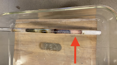
After the combustion column has cooled, you can remove reduced copper that was not used up (and turned into the black oxidized copper) for later use. Put the reduced copper you remove into a lidded glass container. The quartz ash insert should have the end containing ash broken off into the vanadium pentoxide waste container.
Shortly after removing the desiccant column, it is a good idea to clean out this tubing before the magnesium perchlorate becomes rock hard after absorbing atmospheric water vapor from the room. Glass wool and all the magnesium perchlorate should go into a labeled waste container.
Troubleshooting
- Computer Crash – If the IsoDat software and / or computer crash, quit everything and reboot the computer. Open Acquisition and turn the source on by clicking the red sun icon in the upper left portion of the window.
- High backgrounds – Use the mini gas leak detector to check for leaks. A helium leak will show as red LEDs. If the lid is leaking, repeat steps for cleaning the lid and o-ring. You can also change to mass 40 (on the middle cup of CO2…as above) and then use the Argon cylinder to spray connections and watch for increases in mass 40. Try to assess if the high backgrounds are due to an atmospheric leak or are due to something internal. High N2 and Ar might indicate an atmospheric leak. High H2O indicates a wet GC column or a saturated Desiccant Column.
- Unusually low backgrounds – If you are getting values of twice as low or more in Nitrogen and Argon from the historical values seen in the daily log, there may be a leak large enough to prevent carrier gas from moving into the mass spectrometer. For example, Mass 40 has a 20-30 mV signal when it usually is ~100 mV.
- Peak tailing – If your samples have smaller amplitudes and longer scan widths than normal, then they are tailing. This can occur from flow restrictions related to a full insert, a void in the column, improper combustion, low flow rate or a combination therein. The first check would be to see if the insert is filled past the two sets of slits. The second check would be to remove the column and inspect the packing and / or possible voids. The third check is checking the combustion of test samples with standards. The last option would be to check the flow rate of the EA.
- Poor combustion – This can be seen from peak-tailing or a “memory effect” on samples. This occurs when a sample is not receiving enough oxygen or is not getting hot enough (in the case of BaSO4 for complete combustion / thermal decomposition. Peak tailing occurs when a sample sits and smolders leading to a long signal. If a sample does not completely combust, it will finish combusting with the next sample and will affect the resulting values.
Suggested Reading
- Fry B, Silva SR, Kendall C, Anderson RK. (2002) Oxygen isotope corrections for online δ34S analysis. Rapid Communications in Mass Spectrometry 16, 854-858. doi: 10.1002/rcm.651.
- EuroEA3028-HT manual - paper copy in mass spec lab cabinet
